

What Makes 0-10V Dimming Preferred in Track Lighting?
2026-10-26
A lighting specifier is designing the illumination for a retail store with a 12 meter track. The track carries eight track heads, each with a 30 W LED module. The client wants to dim the entire track from a single wall control, from full brightness down to 10 percent for evening cleaning. The specifier evaluates three options: phase-cut dimming, DALI, and 0-10V. Phase-cut dimming is incompatible with the drivers used in the track heads. DALI requires address assignment and commissioning software. 0-10V requires two extra signal wires but no addressing. The specifier selects 0-10V. The decision is not based on preference. It is based on the distributed layout of Track Lighting and the practical requirements of the installation. This guide explains why 0-10V dimming is preferred in track lighting systems.
1. Why Does Track Lighting Need a Dimming Protocol That Matches Its Distributed Layout?
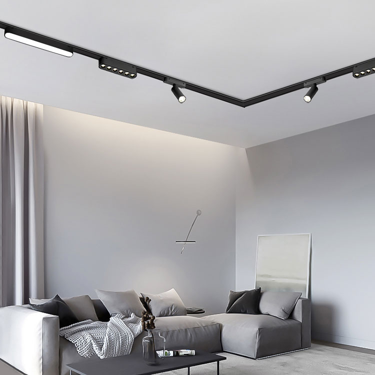
Track Lighting is a distributed system. The fixtures are spread along a track, and the track may run across a ceiling or along a wall. The dimming signal must reach every fixture on the track, regardless of its position. A protocol that requires individual addressing, such as DALI, adds commissioning time for each fixture. A protocol that requires a dedicated control wire to each fixture adds wiring complexity. 0-10V uses a low-voltage analog signal that can be carried on a pair of wires running along the entire track. Every driver on the track receives the same signal and responds identically. This is the fundamental match between the protocol and the layout. In our factory, we manufacture Track Lighting systems with 0-10V dimming drivers as the standard configuration. Zhongshan Dadi Lighting Technology Co., Ltd. has been producing track lighting for over 12 years.
The distributed layout also means that the dimming signal must be immune to the electrical noise generated by the LED drivers themselves. 0-10V is a low-impedance signal, which makes it less susceptible to noise than a high-impedance signal. The signal wires can be routed alongside the power wires without requiring special shielding in most installations. This simplifies the installation and reduces the cost.
2. What Are the Electrical Characteristics That Make 0-10V Reliable in Commercial Spaces?
The 0-10V protocol is defined by IEC 60929. The control voltage ranges from 0 V to 10 V. A voltage of 10 V commands the driver to deliver full output. A voltage of 0 V commands the driver to deliver minimum output or to turn off, depending on the driver design. The control input is typically a high-impedance input that draws less than 1 mA. This low current means that the control signal can be generated by a simple potentiometer or by a multi-channel controller. The table below compares 0-10V with other dimming methods used in track lighting.
| Dimming method | Control signal | Wiring requirement | Addressing required | Typical compatibility |
| 0-10V | Analog 0 – 10 V | Two signal wires | No | Wide (most LED drivers) |
| Phase-cut (TRIAC) | AC phase modulation | No extra wires | No | Limited (driver dependent) |
| DALI | Digital bus | Two signal wires | Yes (each fixture) | DALI-certified drivers only |
| Wireless | RF or Zigbee | None | Yes (pairing) | Proprietary |
The analog nature of 0-10V also provides a predictable dimming curve. The light output is approximately linear with the control voltage, although the exact curve depends on the driver. This predictability makes it easier for the specifier to calculate the light levels at different control settings. In our factory, we test the dimming curve of every 0-10V driver we use. The test data is provided with each Track Lighting order so that the specifier can verify the performance.
3. How Does 0-10V Dimming Simplify Wiring and Commissioning in a Track System?
The wiring for a 0-10V Track Lighting system is straightforward. The mains power is connected to the track conductors. The 0-10V signal wires are connected to a separate pair of conductors in the track or to a separate cable that runs alongside the track. The signal wires are not polarity-sensitive on most drivers, which means the installer does not need to worry about which wire is positive and which is negative. The commissioning process is also simple. The installer sets the minimum light level with a trim potentiometer on the driver, sets the maximum light level with the controller, and verifies that the dimming is smooth across the range. The table below compares the wiring and commissioning effort for 0-10V and DALI in a track system with 8 fixtures.
| Task | 0-10V system | DALI system |
| Signal wiring | Two wires along the track | Two wires along the track |
| Address assignment | None | 8 addresses (one per fixture) |
| Commissioning software | Not required | Required |
| Commissioning time (8 fixtures) | 15 – 30 minutes | 1 – 2 hours |
| Replacement of a fixture | Plug and play | Requires re-addressing |
Specifier's note: The commissioning time saving is significant in a retail rollout with multiple stores. A 0-10V system can be commissioned by the electrical contractor without specialized lighting control software. A DALI system requires a trained commissioning engineer and a software tool. In our factory, we provide a commissioning guide with every 0-10V Track Lighting system. The guide includes the trim procedure and a checklist for verifying the dimming performance. Dadi also offers on-site commissioning support for large projects.
4. Why Does 0-10V Dimming Extend Driver Life and Reduce Flicker in Track Lighting?
Dimming reduces the output current of the LED driver, which reduces the junction temperature of the LEDs and the thermal stress on the driver components. The electrolytic capacitors in the driver are the components most sensitive to temperature. A 10°C reduction in the capacitor temperature can double the capacitor life. Dimming also reduces the output voltage stress on the switching components. The result is a longer driver life. The 0-10V protocol also supports smooth dimming without flicker when the driver uses a constant-current output with a high-frequency PWM stage or a constant-current reduction stage. The table below shows the effect of dimming on driver life for a typical 30 W track head.
< td>< 5%| Dimming level | Driver case temperature | Estimated capacitor life | Flicker level |
| 100% | 65°C | 25,000 hours | < 5% |
| 70% | 58°C | 40,000 hours | < 5% |
| 50% | 52°C | 60,000 hours | |
| 20% | 45°C | 90,000 hours | < 8% |
| 10% | 42°C | 110,000 hours | < 10% |
Flicker is a critical factor in commercial spaces. Staff who work under flickering light report eye strain and headaches. Cameras used for security or broadcasting can capture banding if the flicker frequency is low. A well-designed 0-10V driver maintains a flicker level below 10 percent even at 10 percent dimming. In our factory, we test the flicker of every driver using a flicker meter. The test data is provided with each Track Lighting order. Zhongshan Dadi Lighting Technology Co., Ltd. uses drivers with a flicker-free design for all of our 0-10V track lighting products.
5. What Should Specifiers Verify Before Committing to a 0-10V Track Lighting System?
Before committing to a 0-10V Track Lighting system, the specifier should verify four things. The first is the driver control type. Some drivers are designed to sink current from the controller, and others are designed to source current to the controller. The controller and the driver must be compatible. The second is the dimming range. Some drivers dim only to 10 percent, while others dim to 1 percent or lower. The specifier should confirm that the driver meets the required minimum light level. The third is the controller capacity. The controller has a maximum number of drivers that it can control and a maximum cable length. The specifier should confirm that the track length and the number of fixtures are within the controller's capacity. The fourth is the signal wiring. The signal wires should be separated from the mains wires where possible, and the total cable length should be within the driver's specification. In our factory, we provide a compatibility matrix for our Track Lighting systems and the controllers we recommend. We also provide a wiring diagram that shows the signal and power connections.
We recommend that the specifier request a sample of the track head and the controller for a bench test before the full order. The bench test should verify the dimming range, the flicker level, and the compatibility of the controller and the driver. Zhongshan Dadi Lighting Technology Co., Ltd. provides sample kits for this purpose.
Frequently Asked Questions About 0-10V Dimming in Track Lighting
Summary for Lighting Specifiers and Electrical Contractors
0-10V dimming is preferred in Track Lighting because it matches the distributed layout of the track, it simplifies wiring and commissioning, it extends driver life, and it controls flicker. The protocol is standardized, widely supported, and easy to troubleshoot. The specifier should verify the driver control type, the dimming range, the controller capacity, and the signal wiring before committing to a system. A bench test with a sample track head and controller is recommended before the full order. Zhongshan Dadi Lighting Technology Co., Ltd. has been producing Track Lighting systems with 0-10V dimming for over 12 years and provides full technical support for our customers.