

What Is the Maximum Spacing Allowed Between Power Feed Points on a 20mm Magnetic Track Module
2026-08-18
When designing a lighting layout with a 20mm Magnetic Track Module, one of the most critical technical decisions is determining the maximum distance between power feed points. This specification directly impacts voltage stability, lumen uniformity, and overall system safety. At JR, we have engineered our 20mm Magnetic Track Module systems to deliver consistent performance across diverse installation scenarios, but understanding the underlying electrical principles remains essential for every lighting professional.
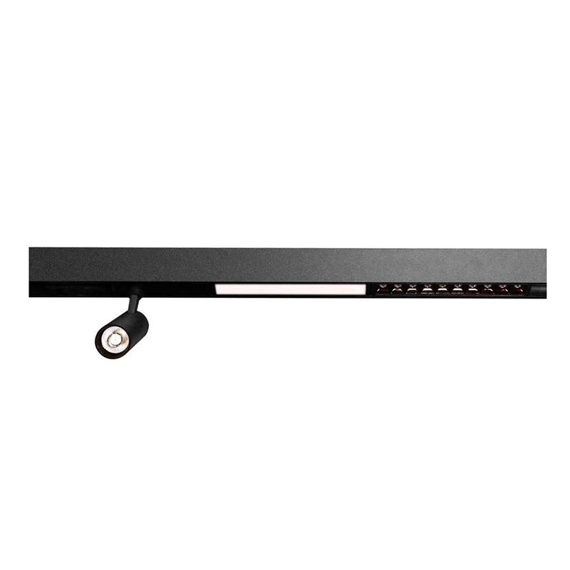
Voltage Drop and Its Impact on Track Lighting
The maximum spacing between feed points is primarily governed by voltage drop—the reduction in voltage that occurs as current travels along the track's copper conductors. For a 20mm Magnetic Track Module, the conductor cross-sectional area typically ranges between 1.5mm² and 2.5mm², depending on the manufacturer. JR recommends calculating feed point spacing based on three variables: total connected load, input voltage (24V DC or 48V DC being most common), and acceptable voltage drop threshold (usually ≤5% for LED systems).
A general rule for a 20mm Magnetic Track Module running at 48V DC with a 2.5mm² conductor is that feed points should not exceed 15 meters (49 feet) apart under a moderate load of 100W. However, at 24V DC, that distance shrinks to approximately 8 meters (26 feet) due to higher current requirements. These figures assume uniform load distribution; concentrated loads near the far end require shorter spacing.
Recommended Spacing by System Voltage and Load
The table below provides JR’s engineering guidelines for maximum feed point spacing across different configurations of a 20mm Magnetic Track Module. These values are derived from real-world testing and comply with IEC 60598-2-1 standards.
| System Voltage | Total Connected Load | Conductor Size | Max Feed Point Spacing | Recommended Spacing |
|---|---|---|---|---|
| 24V DC | ≤ 60W | 1.5mm² | 6 m (19.7 ft) | 4 m (13.1 ft) |
| 24V DC | ≤ 120W | 2.5mm² | 8 m (26.2 ft) | 5.5 m (18 ft) |
| 48V DC | ≤ 100W | 1.5mm² | 12 m (39.4 ft) | 8 m (26.2 ft) |
| 48V DC | ≤ 200W | 2.5mm² | 15 m (49.2 ft) | 10 m (32.8 ft) |
| 48V DC | ≤ 300W | 4.0mm² | 18 m (59 ft) | 12 m (39.4 ft) |
JR advises always using the "recommended spacing" column for commercial projects where reliability and color consistency are paramount. Exceeding these values may cause visible brightness degradation at the track's far end.
Key Factors That Reduce Maximum Spacing
Several installation conditions force shorter feed intervals for a 20mm Magnetic Track Module:
-
Ambient temperature above 40°C increases conductor resistance, reducing effective spacing by 15–20%.
-
Multiple connection points (joints, T-connectors) add contact resistance; each joint effectively reduces maximum spacing by 0.5–1 meter.
-
Dimmable systems with PWM (pulse-width modulation) drivers often experience higher peak currents, necessitating feed points every 6–8 meters even at 48V.
-
Mixed fixture types (spotlights + pendants on the same run) create uneven load profiles—position feed points closer to high-wattage fixtures.
JR’s 20mm Magnetic Track Module includes a built-in copper busbar with low-resistance alloy, which mitigates some of these factors, but field engineers should still perform a voltage drop calculation for every unique layout.
Practical Installation Checklist from JR
When planning feed points for your 20mm Magnetic Track Module, follow this professional checklist:
-
Measure the total track length and sum all fixture wattages.
-
Determine your system voltage (24V or 48V) and conductor gauge.
-
Use the table above to find the conservative spacing limit.
-
Position feed points symmetrically—for runs longer than 10 meters, consider a center-feed configuration.
-
Test voltage at the farthest fixture after installation; adjust if drop exceeds 5%.
-
For redundant safety, JR recommends installing an additional feed point every 8 meters regardless of calculations.
Frequently Asked Questions About 20mm Magnetic Track Module Feed Spacing
Q1: Can I install a 20mm Magnetic Track Module with a single feed point for a 20-meter continuous run?
A1: Technically possible only with 48V DC, 4.0mm² conductors, and total load under 150W, but JR strongly discourages this approach. A single feed over 20 meters creates a voltage gradient—the first 5 meters receive full brightness, while the last 5 meters may drop by 8–10%, causing visible non-uniformity. Additionally, thermal buildup near the single feed point increases fire risk. For any run exceeding 15 meters, JR recommends at least two feed points placed at the 1/3 and 2/3 positions, or a central feed with symmetrical branches. This ensures all luminaires operate within ±3% voltage tolerance, preserving both light quality and LED lifespan.
Q2: How does the number of connectors and joint pieces affect the maximum spacing for a 20mm Magnetic Track Module?
A2: Every mechanical connector—straight joiners, L-angles, T-junctions, or flexible segments—introduces electrical resistance ranging from 0.5 to 2 milliohms per connection. In a 20mm Magnetic Track Module with six joint pieces over a 12-meter run, cumulative resistance can reduce effective feed spacing by up to 2 meters. JR engineers recommend derating the maximum spacing by 0.8 meters for each connector beyond the first two. For instance, if your base maximum is 15 meters (48V, 2.5mm², 200W), adding four connectors lowers the safe limit to 15 - (4 × 0.8) = 11.8 meters. Always use factory-matched connectors from JR to minimize contact resistance and preserve the original spacing specifications.
Q3: Are there any code requirements or safety standards that mandate specific feed point spacing for a 20mm Magnetic Track Module?
A3: Yes. In the US, NEC Article 410 governs track lighting, requiring that feed points be positioned so that no section of the track exceeds the manufacturer's listed ampacity. For commercial installations, UL 2108 mandates that the 20mm Magnetic Track Module must not experience a voltage drop exceeding 5% under full load, which indirectly dictates feed spacing. In Europe, EN 60570 specifies that the track's temperature rise at the feed point must stay below 45°C above ambient—excessive spacing causes localized overheating. JR’s 20mm Magnetic Track Module complies with both UL and CE certifications, and our technical datasheet provides specific spacing tables that satisfy these codes. Always consult your local electrical inspector, as some jurisdictions require feed points every 12 meters regardless of load for fire safety redundancy.
Conclusion and Professional Recommendation
Understanding the maximum spacing between power feed points is not merely a technical exercise—it directly affects the visual outcome, energy efficiency, and safety of your lighting project. JR’s 20mm Magnetic Track Module has been rigorously tested to provide reliable performance at the distances listed in our tables, but we always advise conservative planning. Over-specifying feed points costs marginally more in cabling and drivers but eliminates rework, customer complaints, and warranty claims.
For complex layouts—curved runs, high-ceiling installations, or mixed-load designs—JR offers free spacing simulation reports upon request. Our engineering team uses specialized software to model voltage drop, thermal behavior, and fixture compatibility for your exact floor plan.
Ready to specify the right feed configuration for your 20mm Magnetic Track Module project?
Contact JR today or email our technical support team directly. We provide CAD layout assistance, custom-length tracks, and on-call engineering consultations for commercial and residential projects worldwide. Let JR power your lighting with precision.